Drawing Layout Tip – Bill of Material (BOM) Use
Fully defining large assemblies can be a daunting task. It is a task that cannot be ignored, as a well-defined assembly drawing is necessary to properly convey critical details. Manually labeling everything in an assembly drawing can take days and it is very easy for not all the detail to be captured. A solution to this is to add a Bill of Materials or BOM to the drawing. Modern CAD software (Like SolidWorks – shown in the images below) all have automated means to generate BOMs. This helps automate the process, reduce chances for error and allows for automatic updates as assemblies change.
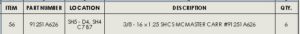
Figure 1: Example Bill of Materials
A BOM is used to fully identify each piece of a larger assembly in a concise way. Figure 1 shows a single line of a Bill of Materials. Starting off the first column, one sees the item number of the part. This is a simple counting of each unique component in an assembly.
The second column is straight forward and displays the part number of the component. The part number may be an internal part number specific to your company or an external part number of a purchased item. If you are purchasing an item off the shelf (COTS – commercial off the shelf) and then are modifying that item by the addition of a hole for example, you would use an internal part number. On the drawing for that specific part, you would then show the suppliers part number for that raw unmodified component.
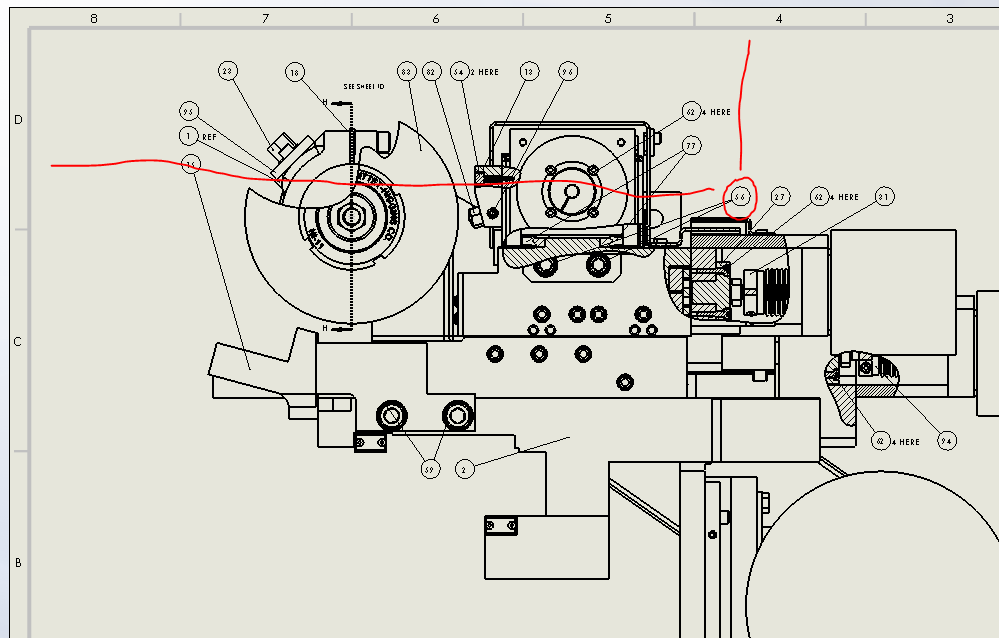
The third column is location. This provides the reader to the exact location of the component in the print. Some will have a tendency to leave this information out. However, having this in place makes the drawing much more readable and useful in finding exactly where the components are located. In the example provided in Figure 1, Item 56 is said to have at least one of the parts on sheet 5 in area D4. Using sheet 5 (SH5), shown in Figure 2, we can locate the part. Starting in zone D (shown as letters in the left hand side of the drawing) then going across the page to zone 4 (shown as numbers at the top of a drawing) a balloon callout showing Item 56 can be found.
Note that when specifying locations on a drawing, the bottom leftmost side of a box fitted around the object is used. So if one were to virtually fit a box around the ‘56’ circled in figure 2, its leftmost bottom corner would have to be located in area D4.
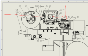
Figure 2: Using the Location Column
The last two columns of the example Bill of Materials shown in Figure 1 provide important details to the reader. Column 4, Description, allows the creator to put a small description of the part so the reader knows what the item is. In the example the description reads “3/8 – 16 x 1.25 SHCS MCMASTER-CARR #91251A626”. This provides detail that it a Socket Head Cap Screw with size 3/8 – 16 x 1.25 that was purchased from McMaster-Carr with part number 91251A626. The part number in this case was already included in column 2 and could for all practicality be left off of the description. In fact, best practice is to only specify things once for drawings. So that if a change were to happen to the part number, then only one item would have to be changed and there would be less opportunity for mistakes or conflicting information. If the part were an internally produced part, then the parts drawing title would suffice for a description.
The last column labeled “QTY.” simply provides the total quantity of the particular item in the assembly. When you locate the balloons for parts that have a quantity more than 1, you have two options. The first is to show a separate balloon for each item. The alternative is to show one balloon with a “x4” or similar reference (“4 HERE” is shown above). As long as it is evident where each instance of the part is in the image of the assembly, there is not an issue of showing one balloon for all instances. But remember that the job of a drawing is to communicate in a clear and concise manner. If it is not obvious, split up the balloons to make it clear where each instance of the part is located.
Sometimes it even makes sense to place multiple balloons adjacent to each other. One case is where there is a hardware assembly of nut, washer and bolt. In that case, one leader line can be placed with 3 balloons with different item numbers. Another case involves the application of lubricants or adhesives. In that case, those are not typically modeled in CAD but balloons are still shown in the appropriate places to indicate where those items should be applied.
There are many other properties that can be used in a Bill of Materials as required. A couple of examples of properties that were not covered in this example include: material and manufacturer of the item.
Using a Bill of Material correctly can allow the drawing creator to fully and efficiently convey details of the assembly to the reader. Contact us today if you have CAD modeling or drawing needs!

Leave a Reply
Want to join the discussion?Feel free to contribute!