What are Casting datums?
We have all seen prints with many datum reference frames on them. The fact that there are multiple sets of datum’s is not an issue and is put in place for functional design reasons. There can be so many that they look like an alphabet soup. But what about raw castings? Generally the functional part datum reference frame(s) have not yet been cut into the parts yet. This where casting datums come into play. They are typically designated as X-Y-Z or Z-Y-X.

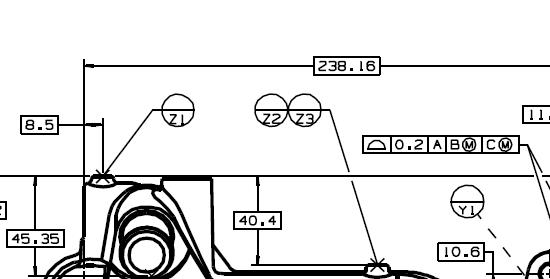
Figure 1: Typical section from a drawing showing casting datums.
Because most prints will not have enough datums to even approach the 24th letter of the alphabet (X), the last 3 are used to designate casting datums. Datums should be made from physical features on a part (not centerlines or ‘off part’ points). Since castings with complex surfaces don’t lend themselves to the typical datum features made from planes or cylinders, datum targets are typically used. The targets can be an odd shaped patch area on a part, circular area or single points on the part surface. Datum target points are commonly used in the castings that we see in our accredited dimensional inspection business. Those castings are complex automotive and aerospace parts that sometimes don’t have a flat surface on them.
Figure 2: Prints can sometimes look like this due to all the datum references.
When reviewing laser scanning data compared to a CAD model (scan to CAD model comparison).The best alignment would be a best fit alignment. All other datum alignments necessarily deviate from that and look worse. Our casting customers will often ask for both alignments (casting datum alignment from the print and a best fit alignment) to understand where deviations are occurring in their parts. Sometimes they can make a prudent modification to one of the datum areas and dramatically bring the part into specification.
The principles are the same for casting datums as they are for machined datums, you must constrain all 6 degrees of freedom of the part and in a specified order. If only datum target points are used, then something like a 3-2-1 arrangement happens. 3 points determine the primary datum, 2 points determine the secondary and 1 point determines the tertiary datum. Note if your casting datum reference frame is not strictly datum target points, then be careful what alignment you use. If your primary datum is a plane for example, then a 3-2-1 alignment will try to align to the average plane which is not how GD&T is applied. GD&T effectively uses the highest 3 points of contact in that plane to establish the datum and not the average plane that a 3-2-1 traditional alignment will use. We have seen many errors that customers have made by confusing this for any type of part.
As always the print needs to specify with basic dimensions where each datum is relative to each other. This is critical for measuring the part correctly. Errors could dramatically alter the results. This is a common source of measurement error. There should be enough information to create a table showing how each datum is related to each other in each of the 3 cardinal directions.
What if the casting datums don’t exist on my part yet?
This happens most often in legacy prints. Over time casting designers have come to find the value in casting datums and for the most part they are included with new designs. If you are stuck with a print without casting datums and must replicate the part, then you should look at a couple of things. If you can find the previous supplier of the part, you could create your casting datums from their machining setups. Because datums are functional to the assembly level and casting datums are meant to be used for setting up for machining final datums, your machining setups should always match your casting datum reference frame.
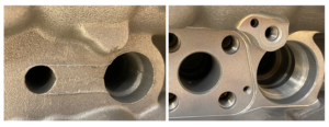
Figure 3: Typical before and after machined casting section.
This obviously doesn’t work if the previous supplier had multiple setups based on different fixturing locations. This would also add variability to their casting and to the final product.
Or if that source is unavailable, then you create your own based on stable holding fixture for machining. Ideally this fixturing would be the same across all of your machining operations used to establish the machined datums. Once the machining datums are established, then those datum reference frames are used to do the balance of the machining. This will yield the best chance for in tolerance parts and lower variability. If you establish these, you should review these with your end customer to document what is being used.
Pick casting datums using a few rules:
- Each datum should cover the largest area possible. Large areas minimize alignment errors. Spread out datum targets so they are able to fixture the part with more stability.
- Datum areas or targets should not be close to parting lines, sprues or other common casting problem areas.
- Datums should not over or under constrain the part – limit all 6 degrees of freedom. There are non-casting exceptions where this would be practical. A common example is automotive windshields which are large flexible parts. In that case, more targets are needed to keep the part from flexing. Typically not an issue with castings.
- Datums are not in functional areas of the part but help balance the part so that consistent and even wall thicknesses are maintained during machining. Consult with the original design engineer if available. They may know of constraints that you are not thinking about that could influence the part.
- A casting datum can be used as a final part datum if it functionally serves the design engineers purposes.
Be sure to include these important features in your next design to help ensure consistent parts. 3D Engineering Solutions stands ready to help you with your design, reverse engineering and inspection needs. Contact us today!


Leave a Reply
Want to join the discussion?Feel free to contribute!