Can you Measure a Gap in CT that is Smaller than the Voxel Size of the Scan?

A common question that we are asked is: what is the resolution of a CT scan for determining gaps or voids or true surface locations? We are also asked: How can you measure a gap between two parts that may be closer than 1 voxel in size? The answer lies in sub-voxel surface determination and in the number of voxels that are involved and continuous surfaces as detailed below.
All of these questions are good ones and on their face very logical concerns. One way to approach the answer is to first understand what a voxel is. A voxel is a VOlumetric piXEL. For CT data, many 2 dimensional x-ray images are taken (thousands usually) and reconstructed into a Voxel data set. The voxel data set consists of millions of voxels stacked together. The voxel itself is cube shaped and so has an edge length and a grayscale value associated with it. That grayscale value helps determine if that area is air or a particular material or piece of a particular material. The image below shows some voxels stacked together.

However, when you look at images of CT data you do not see a stairstep quality to the data as shown in the above image. Instead, it appears smooth and continuous as in the image below.
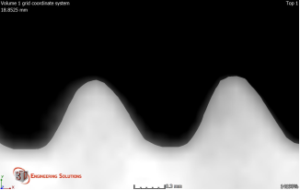
The representation that you are seeing in this image is due to sub voxel surface determination. The actual surfaces that are determined by the software (in this case Volume Graphics 3D Studio Max) run through each voxel and not along the edges of the voxels. If I turn off the visualization of the actual surface and show the same image you will see the voxel edges and the determined surface as shown below.
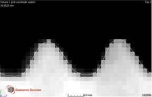
The thin white line going through the voxels (shown here as squares) is where the software has determined that the real surface lies. As I understand it, the surface is determined by looking at the neighboring voxels and their intensity (shown here as grey scale color).
Well, how accurately can you determine the where the true surface is within a voxel?
Basically we can resolve the actual surface to within 1/3 of a voxel according to common industry expectation. The president of Volume Graphics told me that he is confident to within 1/10 of a voxel. Our measurement uncertainty for CT scanning in our 225kV MCT equipment is currently 8 + 0.29L microns (measurement uncertainty is re-evaluated periodically). So, we are able to determine where the surfaces are to within that value at the worst case (which is actually within 2 sigma of the data by convention). We are audited externally and internally to these values.
What about the number and character of the voxels?
The other factor to consider is the number of voxels and their character that make up the void or gap.
For a void (porosity), we like to have 8 voxels of ‘air’ to ensure that the void is real and not simply noisy data. And we would like those minimum 8 voxels to be fairly close to each other and not spread out. The number is more of an industry standard that has been empirically determined. We have proven this out with a few of our customers who actually cut and mounted their parts for comparison to gain confidence in the ability of CT to capture porosity data.
For gaps and cracks, we have a little more flexibility in how the voxels are spaced relative to each other. This is due to the relatively large size and volume of these defects. I would consider a gap as two parts in close contact but not perfectly flat contact (i.e. 2 well machined surfaces in parallel). The parts may instead be wedged or one part may be warped so close intimate contact is not to be had. Gaps usually start with a wide open area open to the world and narrow down to contact. Gaps sometimes also have the advantage of having each side made from dis-similar materials which makes differentiation by the software easier. A crack as shown below generally has symmetric sides (one side is a mirror of the other side) and of the same material.
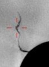
As the gap or crack becomes more narrow and eventually reaches the initiation point, the exact surface location of the initiation is not known (within a few voxels). However, the sides of the gap or crack are easy to determine as shown in the crack image above. The more irregular the gap or crack, the easier it is to distinguish the sides. For cracks that are very fine or gaps with very smooth contact, it may not be possible to distinguish any separation.
Continuous Surfaces
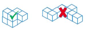
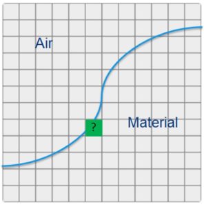
Finally, the software makes reasonable assumptions about continuous surfaces. Because no real surfaces have discontinuities, the software uses this in surface determination. In the image below, the green voxel below will connect the line between the two blue surface lines coming into it. It still uses knowledge about surrounding voxels in this process but also adds the continuous surface constraint.
Likewise if there are two surfaces coming into the same voxel, a similar assumption can be made as shown below.
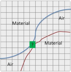
In this way sub-voxel gaps can be captured.
Please contact us for any CT or metrology needs or questions that you might have!


Leave a Reply
Want to join the discussion?Feel free to contribute!