Using a Hybrid Approach to Additive Manufacturing Metrology – CT – CMM
Modern Additive Manufacturing (AM) methods often employ subtractive machining to achieve precise dimensional and surface finish characteristics. This is due to current AM limitations in build precision and surface quality. These hybrid AM / subtractive components also demand a hybrid approach to measurement. Internal features on AM parts are difficult or impossible to non-destructively measure using solely traditional metrology methods and so industrial computed tomography (CT) must also be employed. CT scanning not only allows for precise measurements using metrology CT, but allows for detection of internal defects that are not otherwise able to be seen. However, well machined portions are best served through other measurement methods due to precision requirements and data characteristics. This can necessitate a hybrid measurement approach. However, traditional CT scanning and service providers are not trained as metrologists and do not follow particular standards related to metrology – especially ISO17025. Also complicating measurement is the design and datum reference frames used for additive parts that typically follow a traditional machined component print layout. A layout method following best practices from the casting industry is suggested here. This article explores the methods (GD&T), issues, limitations and current solutions associated with good metrology practices for AM and hybrid AM components.
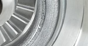
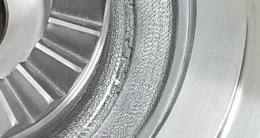
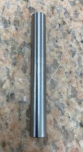
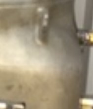
Image of Additive part with as built rough surfaces and machined surfaces. Both additive and subtractive surfaces shown.
AM Measurement Challenges
Additive manufacturing has opened up many new possibilities in design and manufacturing. Several constraints on design and manufacturing have been lifted and that has driven product innovation. With these new design possibilities, new measurement issues have also been born.
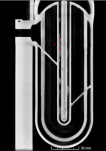
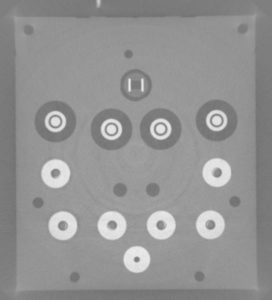
Typical AM part 2D view from CT scan image showing complicated internal features possible with AM
Traditional dimensional metrology is capable of capturing everything that can be reached by probes for contact measurements (touch probes, calipers, pins, blocks, etc) and line of sight for traditional light based measurements (laser, structured light, vision, Chromatic confocal white light). However, internal features and channels that are too small or tortuous to enter with touch instruments and outside of the equipment line of sight of traditional non-contact instruments are problematic. And what if you not only need to see the inside geometry, but want to know about potential build defects in the material itself (porosity, trapped powder, inclusions caused by contamination, delamination). A different method is needed.
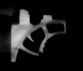
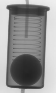
CT scan 2D image showing trapped powder in additive part
Industrial Computed Tomography (CT) scanning fills that need. But like most inspection equipment, it doesn’t do everything. Today there is metrology grade CT equipment that can be brought to bear. Modern CT equipment is now used for more than just detailed internal images and that data is more importantly, traceable. This is assuming you are employing the newer purpose build CT equipment that is designed and made for metrology.
The Need for a Hybrid Inspection Methodology
Because metrology grade CT equipment is able to reach areas otherwise not measurable, does not imply that it is the only equipment that should or needs to be used. Rather a hybrid metrology approach is sometimes required. In fact for most typical inspections, such an approach is already used.
A typical inspection might already employ one or more different CMMs, hand tools and light scanning methods. This is done because certain instruments are more ideally suited for a particular measurement than others or have better measurement uncertainty. Take gage pins for example. There is no better way to functionally measure a hole diameter than with a gage pin. The gage pin is a functional measure of the size of mating piece that will completely fill a particular hole. Other measurement methods are sub optimal. Those methods have measurement uncertainties that will bias the size of the diameter measurement and are therefore not as functional as a gage pin. A gage pin on the other hand is of a well-known size and completely covers and engages the hole surfaces versus only sampling select surface points as is seen with CMMs. Of course, if the tolerance for a particular hole is so large and the alternate method has a measurement uncertainty that is sufficiently small, then a gage pin is not necessary then other methods may serve well.
Combining traditional dimensional measurement technologies with metrology grade CT scanning is just the next step in increasing our arsenal of measurement techniques. The goal is to use the right tool for the specific measurement in question.
Use a two dollar gage pin or a million dollar plus CT machine to measure your parts … or both?
CT Scanning and its Limitations
Each measurement technology also has its limitations. CT scanning has limitations as well. CT scanning first starts with many x-ray images. The process collects thousands of 2 dimensional x-ray images of an article from many orientations and then combines that data into a fully 3 dimensional voxel data set (a voxel is a volumetric pixel).
X-rays have been used for defect detection for quite a while and some might use it to collect dimensional information as well. However, a single x-ray has some issues that are addressed by CT scanning. When the x-rays enter and pass through a part and are then read by the x-ray detector, the image that is created is not dimensionally at the same scale throughout the image. This parallax effect is due to magnification. The effect makes features of the measured part which are closer to the X-ray source larger than those features further away from the x-ray source. So the image is difficult to measure directly.
Typical X-ray Image
As an analogy of this magnification effect, consider a flashlight made to shine on a wall. The flashlight is the x-ray source (x-rays are in fact photons) and the wall is a digital x-ray detector made of pixels. When you put an object in between the two a shadow is cast on the wall. If you move the object closer to the flashlight, then the shadow grows (or is magnified on the wall). If you move the object further from the flashlight, the shadow shrinks. This is the magnification effect that happens on each section of a part that is x-rayed. So sections of the part closer to the x-ray source are more magnified and sections of the object further from the x-ray source appear reduced in size (less magnified).
Industrial CT scanning gets past this issue by combining data from thousands of x-rays taken as the part rotates in front of the x-ray source and is collected by the x-ray detector. The software that combines this data uses all of this variable information to correct for the parallax effect so that the final voxel data set is magnified correctly throughout.
CT scan image after reconstruction – 3D view showing internal and external detail
As long as you can accurately scale the object you are CT scanning you can be assured of the dimensional data that you receive in the voxel data set. Traditionally, CT scanning was used to obtain images of the object only with little regard for the exactitude of the dimensions presented. In fact, I know of CT scanner operations that employ tape measures to determine the source to detector distances!
Modern metrology grade CT scanners employ several techniques to ensure that the scaling is well understood. The distance between the source and object stage and detector is laser calibrated on a regular basis (not only for distance but for squaring of the detector to the source), the position of the object on the measurement stage is well known by use of encoders and feedback loops, the temperature of the system is maintained to a high degree of certainty and the structures that hold each of these elements (source, object and detector) are made from very stable and substantial materials (granite and steel). All of these items drive the cost of this specialized CT equipment higher than the already expensive standard equipment. However, quality equipment is always worth the cost.
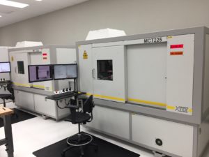
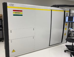
Typical Metrology Grade CT equipment
The limitations associated with CT scanning involve the ability of the x-rays to penetrate the part and then accumulate enough data on the detector. So the thickness and the density of the parts being measured are a factor. Part size limitations come from the size of the CT equipment, the power of the equipment and physics limitations in the distance between the x-ray source and the detector.
The kV rating of CT equipment describes its ability to penetrate materials. The higher the kV the better penetration is achieved. The amperage of the equipment (usually in mA) dictates the rate of accumulation of x-rays on a detector. The higher the amperage, the faster your x-rays images are able to be made. Generally CT scanners are commercially available up to 450kV equipment. There are some 600kV machines available but these are rare and the technology is still being worked out by the manufacturer. MeV (millions of electron volts versus thousands of electron volts) machines are available from some suppliers but these are quite expensive to purchase and the data quality is lower due to poor spot size. This limits the resolution of the final data.
More power is needed to penetrate very thick materials and with the increased power the resolution is decreased sometimes to the point of being not helpful. The critical characteristic for CT scanners is spot size. Generally speaking, the lower the kV the better the spot size is available. Spot size ranges from micro focus (under 100 microns) to mini focus (over 100 microns). Spot size is directly related to resolution and that is directly related to accuracy for CT scanning. Your service provider or OEM can tell you what resolution you can expect for a particular part size. This is a key question to ask and is the difference between good data and relatively useless data.
Higher Kv is needed for more dense or thick parts. The CT process is set up by checking the x-ray penetration through the thickest and most dense portion of the part. If you are not able to fully penetrate the part, then the data will just come out very noisy in that area (not very useable). The thickness of the part is determined by not measuring the outside dimensions of the part but the accumulated thickness of each wall or section of the part that an x-ray would see as it tries to pass through the part. For example, we are able to generally get through about 3 inches of accumulated thickness of steel or around 9-10 inches of Aluminum in our 450kV equipment. We have successfully imaged 11 inches of Aluminum. However, the data was very noisy and required much manual clean up.
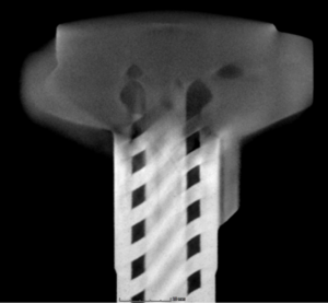
Thick and dense AM part with insufficient penetration at the top of the part. Not very usable in that area.
The size of the part can also be a limiting factor for CT scanning. The largest commercially available panel is currently a 16”x16” panel. For our scanners, this means a single scan can capture approximately the volume of a 9.5” diameter cylinder which is 9.5” tall. Because the object can only get so close to the panel, the full 16” cannot be achieved. This is related to the magnification effect described above. However, multiple scans can capture longer parts (or by use of helical scanning). Some systems offer what is called ‘panel shift’ technology which takes multiple images for each x-ray image to capture larger parts. This makes the scans take longer but allows a larger part size to be scanned. Using single line LDA (Linear Diode Array) or CLDA (Curved LDA) will allow a larger part width of around 17”-20” inches. However this takes longer to scan as LDAs only capture 1 line of data at a time instead of up to 2000 lines at a time from a 16” x 16” panel scan.
CLDA scan of metallic assembly with multiple materials. This single slice CT took 3 minutes and looks good!
If you have a larger part and are only interested in a certain section or area of the part, the option exists to perform a partial volume scan of just that region of interest. This may require a machine with a walk in room instead of a cabinet if the part is very large. Basically x-rays are taken of just a certain section of the part and the sections not falling on the detector are calculated out by the software. The data looks like the area of interest has been placed into a cylinder. You could take multiple areas of interest and then later combine them in the CT analysis software. However, that can require tedious work to achieve a very good alignment.
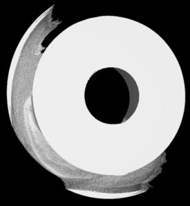
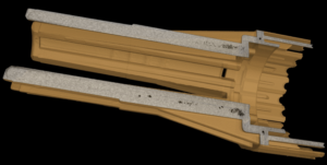
CT partial volume scan. All material outside of the limits of scanning is shown as thin cylindrical slivers.
Traditional CMM and Light Based Technologies
For features of a part that are reachable by touch probes or are in the scanning equipment’s line of sight, it may be best to use a traditional technology. While a CT scan will capture the entire part in most cases (partial volume scans being the exception), the measurement uncertainty requirements or noise from difficult CT scans may dictate a different method. Our metrology grade CT scanners are generally capable of measurement uncertainties of around 13 microns (which is very good). You may have cases where better uncertainties are needed. The character of the CT data surface quality is generally lower than with light based scanners and may be another reason to choose that. If there is a higher level of noise, the surface quality issues can be exaggerated. However, for certain materials the surface quality can be quite good from a CT scan. We have particularly good success from Titanium and plastic parts for surface quality and generally have lower surface quality from high Nickel alloys or very thick parts. For reverse engineering projects, we often combine CT data and light based scanning data together to offer the best of both worlds.
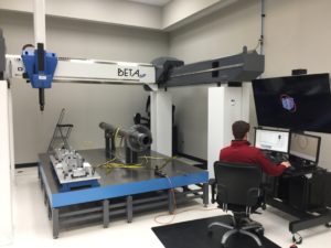
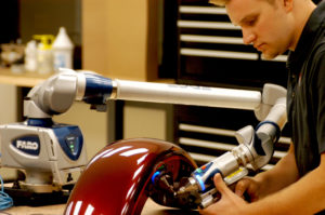
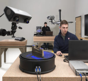
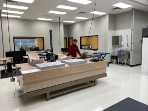
Three typical data collection methods: Gantry CMM, portable CMM and structured light scanner
If your parts have high density or thickness issues and the CT data is noisy in several areas, touch or light based scanning will yield better data sets to work with. Sometimes these issues only occur in one area of a part and the balance of the part yields very good data. We will then augment the CT data with other data as it makes sense from a measurement uncertainty standpoint and from a data clean up stand point. We will always choose the most efficient methods that meet the requirements.
This hybrid approach to metrology is common when trying to avoid natural discrepancies associated with various types of measurement equipment. Understanding CT scanning’s strengths and weaknesses will allow you to know when to use alternative methods.
With modern metrology software, it is relatively simple to combine multiple data sets accurately together. This is critical in a hybrid inspection scheme for picking up datum references that cross various data sets.
Good Metrology Practices – Casting Datums – GD&T
When approaching additive manufacturing from a design perspective, a casting based drawing layout approach should probably be used. In designing cast components that later receive machined features, prints are laid with ZYX datums first. The ZYX datum structure as opposed to the familiar ABC structure is a way to indicate that the initial datum structure is to be used as a temporary datum reference frame (DRF). This is later replaced with a DRF for the finished and machined part. The ZYX datums are used to locate the part for machining in the ABC datums. Because many cast products require precision locating features to be machined in after casting, this temporary structure allows the manufacturer to understand how they are to fixture the part prior to machining. Our experience indicates that this is also one of the typical sources of error in the manufacturing process. Often times, the manufacturer is not aware of the purpose of this datum scheme and mounts the parts for machining in a different way (perhaps one that is easier or more convenient for them). However, following the design engineers setup or temporary datum structure ensures consistency between different manufacturers and ultimately limits the liability of the manufacturer.
Images of 2 as built AM surfaces which appear similar to cast surfaces
For many casting datum (XYZ or ZYX) reference frames, datum target points are used instead of larger flat surfaces or other geometry. Due to the rough nature of castings and the possibility of odd unintended features on the cast surfaces specific points are used. It is then less likely that the points used to locate the datum reference frame will induce variability as would an unexpected glob of material on an otherwise flat surface. Typically you might see 3 X, 2Y and 1Z target points (or ZYX order) used to define the DRF. This is the number of target points needed to definitely constrain a rigid body. These targets are applied in 3 mutually orthogonal directions.
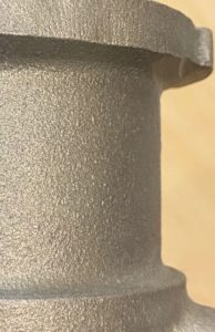
Image of a typical cast surface. Compare to AM surfaces above.
Additive manufactured parts have similar characteristics as cast parts. They tend to be rougher than other manufacturing methods and they are sometimes subject to some small and odd features or other unintended defects. Like castings, many times these oddities or rough areas are in places that have little or no bearing on the function of the part and are otherwise acceptable. Applying a casting datum structure to additive parts will gain the benefits also seen in cast parts including the assurance of consistent results from machined surfaces.
The Role of ISO Standards and Which One Applies for Metrology
CT scanning is still a relatively new and expensive technology. It is needed in the inspection of the majority of complex additive parts. Many additive suppliers are not able to justify the quantity of equipment and experienced staff required to complete inspections in CT. Because of this, outside sources may need to be used.
A good metrologist is the difference.
The role of outside service providers is to help meet the need for hybrid AM metrology. Expensive CT equipment combined with a low quantity of trained metrologists in CT lends itself to outside support for many companies. Generally small to medium sized companies use this advantage. However, even large companies can see benefits. Large companies sometimes have their own CT equipment but we find that engineers have a difficult time getting time on the equipment for qualifying new components due to production needs. Small and medium sized companies have trouble with the intense capitalization needs and finding/hiring experienced and qualified staff. Unfortunately, the shortage of qualified staff (metrologists) in CT will take much time to remedy. CT scanning still has an ‘art’ aspect associated with it even with the advent of push button CT scanning offered by several suppliers. Depth of experience in CT matters and experience as a metrologist also matters. Better CT scanning suppliers will be metrology companies who also have CT versus CT scanning only companies. The latter tend to focus solely on defect determination and not metrology.
Since metrology based CT scanning is a new concept and most suppliers of CT scanning are not metrologists nor do they have metrology based equipment, it would be advantageous to have a standard that could be used to help distinguish between suppliers who are taking CT images for simple defect detection versus also able to perform traceable measurements on those parts.
ISO has such a standard that is particularly indicated for dimensional measurements – ISO7025. According to their website: “ISO/IEC 17025 enables laboratories to demonstrate that they operate competently and generate valid results, thereby promoting confidence in their work both nationally and around the world”. The key focus being the words “competently” and “promoting confidence”.
So this standard has its role in ensuring consistent quality for all measurements. It also ensures that the metrologists are well trained to accomplish the scope of their accreditation.
This Article Explains the Difference Between ISO9001 and AS9102 and ISO17025
You may see certain CT scanning suppliers tout an ISO9001 or an AS9102 certification. Be wary – While these in themselves are ok, they are not metrology specific and merely ensure that adequate management systems are in place to establish a framework. There is no competency or proficiency component to them!
We have seen issues from CT scanning suppliers certified to the ISO9001 and AS9102 standards deliver clearly errant results. Because these 2 standards are well known and most purchasing agents are not even aware of ISO17025 or the limitations of the other two standards, certain assumptions about competence in metrology are made to their detriment. Make sure that your purchasing agents understand. If your supplier is certified to ISO17025, they are compliant with and covered by both ISO9001 and AS9102 for dimensional inspection.
ISO17025 is also the standard you would look for when shopping for CMM inspection and other traditional inspection sources. Some of the requirements that make this valuable for manufacturers and their quality staff include the yearly auditing requirement for metrology specific items, 3rd party proficiency testing and measurement uncertainty creation and verification. This ensures traceability to national standards and quality of the results.
Other Ways to Use CT Scanning
In addition to being able to locate defects inside of your parts and being able to accurately measure your parts, CT scanning offers some additional benefits that may not be as well known.
With CT scanning, you are able to see inside of your parts before machining them and that can be of great value. If you knew that machining a seal face into a part would open up a void, then you could save time by not machining that part. If the part had many sealing surfaces that needed to be machined, then knowing ahead of time if any of them would reveal an un-sealable surface would be of even greater value. CT scanning can provide that information.
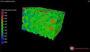
Strut thickness evaluation in CT scanning. Another option.
Basically, you would overlay the CT data (the voxel data set) to the finished machined model. The software will then show any areas that reveal voids in the material on machined surfaces. While we are specifically talking about additive parts that are later machined in a hybrid fashion, this could equally apply to other raw stock materials.
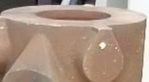
The software is able to distinguish density of material very well. If the additive equipment used to generate your parts were still contaminated with a different material, this would show up in a CT scan as an inclusion. CT scanners are able to easily distinguish higher and lower densities from each other as long as the density difference is sufficiently great enough. We have seen these most often in pull test dog bones. The idea of a dog bone sample is that you shape material into rough the shape of a dog bone and put it into a pull tester to obtain a stress/strain curve information (or true stress/strain curve). This information is used to characterize the material or to verify the properties of a particular build. These parts are removed from the build plate and ground down to a very smooth surface in order that the surface texture does not directly affect the pull test. If contamination from a previous material was present in the machine, it can often make it into the dog bone. CT scans are great at revealing this. if you find contamination in your pull test sample, it is also likely in your build.
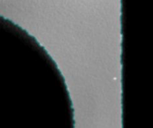
White dot to the right side is contamination from a more dense material in this AM build.
CT scanners are at their core x-ray machines. They can always be pressed into doing quick ‘live x-ray’ work for finding gross defects. However, a CT scan generally is much better at finding defects but takes longer. However, having a quick way to check is a nice added benefit. Equally beneficial is creating x-ray movies to see the workings of an assembly to help troubleshoot internal issues.
CT scanning using metrology methods and inspections using CT scanning and traditional inspection methods are ever increasing. Controlling the quality of you inspections of additive components through the use of several measurement technologies will ensure that you have high confidence in your builds. Contact us today to see how we can help you with your AM metrology needs!


Leave a Reply
Want to join the discussion?Feel free to contribute!