How to Properly Use Point Probes on FARO CMMs
Covered Topics: Point Probe Accuracy, Sharp Tip Point Probes, On-Site Measurement, How to Accurately Measure Trim Lines, Creating Non-Standard FARO Probes, Using Multiple Probes in One Inspection Session, Changing Probes During an Inspection
Point probes are typically thought of as a very sharp point and are assumed to have zero radius. During a recent on-site inspection we discovered that this assumption is not the best one. We discovered the initial discrepancy when using one of our FARO arms and multiple probes in one inspection. We used a 3mm ball probe and a sharp tipped point probe. After calibrating and then setting up the reference frame and measuring a few features with the 3mm ball probe, we switched to the point probe, calibrated the point probe and began to continue measuring.
Typically we do not need to change probes during measurement. However, for this case we needed to probe trim lines that followed a non-planar path. So using a ball probe would have introduced a larger error in the non-planar areas. This is because the trim lines were not on a simple plane. So we could not compensate the ball probe with a simple plane. The trim lines that were at an angle would have required a separate probed plane for each point (not practical from a time standpoint) or use a compensation point (already known to yield poor accuracy).It was shortly thereafter that some of the results from the point probe started to not make sense. As a check we created some features to compare to previous features and discovered a difference of 1.3mm to 1.5mm in values measured with the 3mm ball probe and sharp point probe. At first we thought that the part had been bumped or the tripod that the FARO was mounted on was bumped. We quickly eliminated these as possibilities by retrying and being especially cautious of these items. No resolution. We thought that it might be a software issue or a hardware issue (although not likely).
Once we brought the arm back to the lab and set everything up on one of our granite surfaces we determined the differences to be on the order of 0.5mm consistently. We believe the initial 1.3-1.5mm values came from one of several possibilities: the number of points used during calibration (about 200) versus the greater than 500 points used back in the lab and standard practice, the granite surface and nice clamping arrangement.
This still left us with the dilemma of why there was a difference at all. We had two different point probes available to us. We tried both and found that each had a different off-set from the ball probes – but consistent. The second point probe was an older one salvaged off of an older arm. Both are pictured below shown on an optical comparator. Once we saw how different the two probes were we understood why there might be a difference.
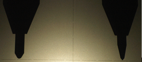
FIGURE 1: Optical comparator view of 2 point probes. A newer one (left) and an older one (right). Note the radius on each tip.
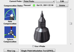
With this information and a little brainstorming we came up with the now obvious fact that the point probes do not have a zero radius! The assumption to date had been a zero (or very close to zero) radius. This is clearly not so as seen in Figure 1. In fact the PolyWorks plugin from FARO shown in Figure 2 below shows a zero value for the radius (Probe Diameter).
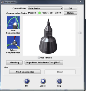
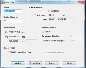
FIGURE 2: The standard plugin for a point probe which shows a zero value for the radius of the probe (Probe Diameter).
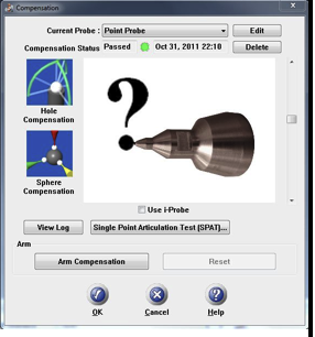
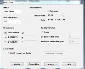
FIGURE 3: The same plugin once the value of the radius has been changed from zero to our estimated value. The question mark and generic probe appears whenever the standard probe values have been changed.
After this revelation, the next step was to determine the radius to use. We used a 1-2-3 block to probe all 3 principle directions (X-Y-Z) and determine what value to use. And in fact, each difference was very consistently offset from the ball probe measurement. This consistantly equal offset value in each direction was another indication to us that in fact we needed to use a spherical radius value for our point probes.
We still had some small variations in the readings (X-Y-Z), so we took an average value and input this into the radius for the point probe (Figure 3). The result – Success!
The difference values between probing with a ball probe and the point probe (with radius value) were very good. We saw differences from 0.004mm to 0.015mm. We will work to tweak these values a bit but feel as though we now have a good process to work with.
In the past we had been told that the point probes were not very accurate or that we would not be pleased with the results from using one. We believe that we have figured out the missing link for achieving reasonable accuracy with this probe.
Note that since these probes are all relatively sharp, you should recheck the radius of your sharp point probe before each inspection to be sure that it has not worn significantly or developed a burr. Either might give you erroneous results. We suggest probing a 1-2-3 or similar block and looking at the X-Y-Z values taken on multiple faces to deterimine a proper spherical radius to use.

Leave a Reply
Want to join the discussion?Feel free to contribute!