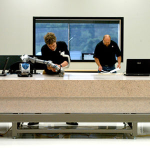
Dimensional Inspection
We are experts at dimensional inspection and can provide advice for your dimensional inspection project whether it is a First Article Inspection, CMM measurement services, routine dimensional inspection services and checks, or troubleshooting an issue within the manufacturing process. Using experienced and trained reverse engineering and engineering metrologists and the best equipment available, let 3D Engineering Solutions solve your critical needs with dimensional inspection services. The dimensional inspection services we offer can help you today!
For those not well versed in the process called dimensional metrology, many aspects can be confusing. Use our expertise to help you navigate your important dimensional inspection measuring requirements. The information below is provided as a basic starting point for understanding some good dimensional metrology practices and it can also answer some common dimensional inspection questions. Please contact us for more detail about dimensional metrology, dimension inspection services, or to request a quote. We are able to turn around most of our quotes for various dimensional inspection services within a few hours.
What is Dimensional Inspection?
Simply put, dimensional inspection is the acquisition of 1, 2 or 3-dimensional data about a measurand (that, what is being measured) and comparing that result to a print specification and tolerance.
What is a dimensional inspection report?
A dimensional inspection report is an easy-to-read summary of the inspection. It will include a print with ballooned dimensions. This is usually a circled or squared number adjacent to each print dimension. The balloons should include each case of a multiple instance dimension referenced. So, a pattern of 5 holes will have a ballooned number for each of the five holes.
An image of the inspection set up with your part should be clearly shown to allow any repeat or future measurements. We find that having this included in the report answers many questions and improves overall communication.
A written method section should be included that lists any assumptions or preparation that was needed for the numerous measurement opportunities that exist. Many times, circumstances require an explanation of a method or measurement process and technique. This ‘methods’ section allows us to communicate more specific detail or specific customer requests and how they were handled.
An inspection certificate or equivalent information should be shown, which would include all of the dimensional inspection equipment used (manufacturer, model and serial number), calibration due date and certification number, if any, the customers PO number, a description of the part(s) being measured, who measured the parts, when the parts were measured, what temperature were the parts measured at, where the parts were measured (at 3DES’ lab or at the customer’s site) and the estimated measurement uncertainty from each piece of dimensional inspection equipment.
The goal of the dimensional inspection report is to give enough information to be able to repeat the same measurements at a different location and/or to help understand any differences that might be due to the method and equipment and assumptions used.
What is the Relevance of a Dimensional Measurement to the Manufacturing Engineer?
Accurate inspection dimensions are critical to the Manufacturing Engineer (ME). A large part of an ME’s job is to troubleshoot and correct issues like inconsistent dimensional measurement that can occur on the manufacturing line. Knowing the root cause of the problem is key to implementing a long-term solution and not having to fight the same dimensional measurement issue again and again. Accurate and reliable dimensional information on the parts is critical to understand the baseline conditions. Use 3D Engineering Solutions expertise to help satisfy these measurement needs.
As a starting point, there is an assumption the parts are all manufactured to the design intent as communicated in the print. You further assume that if they are made to the design, then the part and assembly should fit and function well. Part of the ME’s job in troubleshooting is to confirm that the parts are made to print and then to correct them or suggest a design change if they cannot be made to print. If they are made to print, then their job becomes helping to detect any overlooked design error.
If there is an unintended design error, then tolerance stacking should be employed to determine possible solutions. 3D Engineering Solutions can help you and your design team with the tolerance stacking calculations as a basis to suggest feature or tolerance changes in the design.
A proper and accurate dimensional inspection report will provide enough data for the ME to make an informed decision. Poor or not well written dimensional inspections can provide conflicting or confusing information.
What are Factors That Should be considered when evaluating the Correctness of Dimensional Measurements on Manufactured Parts?
There are several key factors that influence the correctness of an inspection dimension. Most of these deal with assumptions that are made but not explicitly stated.
Condition of the part being measured:
The parts themselves can be influenced by a few conditions, including their temperature (which would make them grow or shrink), cleanliness (which will interfere with measuring the actual surfaces vs dirt), specularity for light-based measurements (which add noise to the measurements), deflection due to gravity (which mostly affects the relevant characteristics of large or flexible parts) and surface hardness (which for elastomers or flexible materials can yield incorrect results for probing due to deflection of the part). Documenting these surface conditions is another good reason to include setup images and a method section in the inspection report.
Condition of the measurement surface:
Sometimes measurements of larger parts have to take place on concrete floors, which are generally not flat. Gravity can easily distort your part to the non-flat shape of a surface. Be cautious of using wooden tables or any unsteady surface. They not only can distort your part but can cause other measurement errors. In our lab, we use granite and ground steel as our measurement surfaces. The cleanliness of the surface matters. If the measurement surface is dirty or greasy, it can allow movement of the part during measurement, add ‘thickness’ or transfer to the part and can lead to poor measurement results and poor measurement data.
Standards:
The standards to be used for any inspection should be found from the print. This might say, for example, that the GD&T is to be interpreted to ASME Y14.5. It might also say that an appropriate ISO specification should be used. Issues can arise when customer-specific standards for measuring should apply (due to customer request) but it is not explicitly indicated on the print. This goes for not only interpreting how to take the dimension but for how to report the dimension as well. One common example is in the reporting of positional or profile tolerances. Some companies ask that only the worst-case profile deviation be indicated (the point furthest from the nominal surface) instead of a profile value that directly relates to the profile tolerance. If the profile tolerance is 0.030 and the worst deviation from the nominal is 0.018, some may ask to have the 0.018 reported instead of the proper value of 0.036. The obvious confusion is that 0.018 appears to pass the specification. However, it in fact fails the profile specification!
Technician and customer training:
We see many measurement equipment operators who understand how to operate the equipment but do not understand dimensional metrology well. These are typically very bright people who just have not yet been trained well on conventional metrology measurements. 3D Engineering Solutions offers customized training for your staff. The metrologist has much latitude in where they take measurements on a surface and how many points that they take or consider for the measurement. Data collection usually involves some stray or spurious data that needs to be removed. It is up to a well-trained metrologist to make those decisions based on their knowledge of the application. A common error for a not well-trained metrologist is to use only the minimum number of points to determine a feature. If a circle is measured, they would be tempted to use only 3 points (3 points determine a circle). However, oversampling of the feature is required to obtain good data. We recommend taking many more points than the minimum. This will make your program longer; however, that the data will be more reliable. These ‘extra’ points provide the metrologist with an avenue to remove spurious or obvious bad data and still have enough information to report the dimension. Another common example is measuring cylinders as circles. Circles are easier to accurately measure but lose the 3-dimensional aspect that you get from a cylinder. You could measure a circle that is in specification, but the angle of the hole may be out of specification!
Accuracy and Measurement Uncertainty:
Not all equipment is suited for any measurement. The accuracy and by extension the measurement uncertainty of the method and equipment must be taken into account. Typically, a Test Uncertainty Ratio (TUR) of 10:1 (equipment that is 10 times better than the tolerance you are measuring) is the standard. With tighter tolerance that we see today, a TUR of 4:1 is acceptable many times. We have even seen TURs of 2:1 or less as sometimes that is the only practical way to get results. The default mode is to make the uncertainty from your measurement only a small part of the result. You must also consider when the measured result is close to one of the specification limits. If the uncertainty in the measurement straddles the specification limit, you have to make a judgement if the result is truly acceptable or out of the specification. This can be handled in the methods section of the inspection report and should be discussed with the customer. 3DES will indicate any assumptions made in regards to measurement uncertainty.
Type of equipment:
Not every piece of measurement equipment is suited to every measurement. The TUR explanation above is one example. Another common one is the measurement of holes. Because measurement equipment has an uncertainty about each point measured, this can lead to some misleading information about tightly controlled hole measurements. If you have a tightly fitted hole, then a common gage pin is often the best method to check for diameter. Even a very accurate CMM has uncertainty that can make the hole appear smaller or larger than it actually is. However, a gage pin will always either fit or not fit. Simple equipment is sometimes the best to use.
Calibration of equipment:
Calibration certificate information should always be provided with the inspection report. You should know when the equipment is due for calibration. Not only to see if the equipment is technically in specification, but to see if it is close to the re-calibration date. A good lab will perform periodic checks and calibrations before your measurements to ensure that the equipment is operating in specification and as intended.
Worn probes:
For fixed CMM inspections, the spherical probe tips that are used can become worn. They can wear flat spots on them through constant use that will alter the measurements.
Measurement Technique:
Common examples of issues related to technique involve shanking a CMM probe on a surface instead of contacting the probe sphere and using calipers (1 D instrument) to measure tightly controlled 2D or 3D dimensions. The inclusion of setup images in the inspection report will help alleviate these concerns.
Reference surfaces:
Does the print show which surfaces are to be considered the reference surface? These datums are important for understanding and for consistent measurement. Take for example the measurement of two ends of a cube. Since no real objects are perfect, one of the flat ends is not going to be parallel with the other. When that is the case, you must specify which surface is the reference surface. Why? Because you will get 2 different results depending on which one is used as the reference. A well written print does not leave this to interpretation. If you have to choose one surface, this could then be recorded in the ‘methods’ section of the report.
Spot size, pixel size:
Each measurement instrument has either a specified contact area or image spot / pixel size. These help form the limits of the ability of the equipment to resolve measurements. For laser and structured light this is a pixel size of the camera measuring the light, for CT scanning this is the x-ray source spot size and the detector pixel size, for a CMM it can be the contact area of the spherical probe. For precise measurements, certain of this equipment is not well suited for use in certain measurements because of these limitations. In long range laser scanning for example, the spot size can generate points hanging in space between a table and floor. This is because the laser spot is large enough near the edge of the table to overhang the table. That spot sees both the edge of the table and the adjacent floor and will put a data point in between them.
Construction of dimensions:
The simplest and most direct measurement is the best for quality control. You may be sometimes forced into constructing multiple features to get one measurement, but keep it minimized to the smallest possible concatenation of features. Each feature you add to a measurement increases the individual measurement uncertainty of that dimension.
Type of measurement:
Certain features are difficult to measure and there are often other similar measurements that can yield better results. Radii are some of the most difficult features to measure. They consist of about ¼ of a full circle (so there are no opposite points to measure for confirmation) and they blend into the surrounding surfaces. It is easy to measure into the blend area and it is easy to not measure enough of the radius. In either case, the uncertainty of these measurements will be very high. A good way to combat this is to use a profile measurement instead. Typically, radii are used for a strengthening feature or to help allow clearance or to accommodate a the manufacturing processes of an operation. All of those uses can be verified with a profile measurement instead.
Software assumptions:
Be careful of which measurement software you use in an inspection. Some may have legacy methods of measurement included in them by default. Since measurement standards have developed over time, there may be options in the measurement software to accommodate older standards. Sometimes the software manufacturers allow you to choose this as an option and sometimes this is just the default setting.
Please contact 3D Engineering Solutions today and learn how we can help you with quality control and so much more for your next project.
FAQs
-
What Is A First Article Inspection In The Field Of Dimensional Inspection Services?
- First article Inspection (FAI), is the process of planning, manufacturing, and verifying a business, organization, or manufacturer’s production process. A first article inspection report (FAIR) is a document that is used to certify that each sample was produced and inspected according to what the customer is looking for. A first article inspection is one of the many different types of article inspections that exist for quality control.

